Considerations For Testing and Simulation of MIL-STD- 1760E/HS1760 Avionics Interfaces
MIL-STD-1760, a Department of Defense Interface Standard, was developed to reduce the proliferation of interfaces between aircraft and their stores, and instead to promote interoperability between weapons and aircraft platforms.
The original version of the MIL-STD-1760 defined a standardized electrical interface and connector that included both digital and analog databuses, a standardized message protocol (MIL-STD- 1553), power, and discrete signals.
In 2007, the latest version of MIL-STD-1760 was released. MIL-STD-1760E, employed the previously unused High Bandwidth 2 and High Bandwidth 4 pins of the standardized MIL-STD-1760 connector. These pins were utilized to carry a Fibre Channel based high speed digital databus, FC-AE-1553 which is an adaptation of MIL-STD-1553 for Fibre Channel.
This paper provides a brief technical overview of the HS1760 databus and related standardized protocols and also provides an overview of the key technical considerations that must be accounted for when designing test and simulation equipment used to test various aircraft systems and stores which employ the MIL-STD-1760E interface.
I. INTRODUCTION TO MIL-STD-1760
The MIL-STD-1760 interface standard was created to standardize the electrical (and fiber optic) interconnect between an aircraft and its stores. Aircraft stores are any device intended to be carried externally on the aircraft. Stores can be weapons, auxiliary fuel tanks, and sensor pods all of which can be controlled from the aircraft.
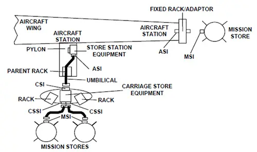
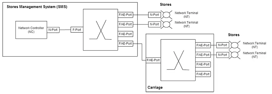
As shown in Fig 1, MIL-STD-1760 provides for a variety of aircraft/store configurations. In the most simple case, the standard defines the requirements at the Aircraft Station Interface (ASI), and the Mission Store Interface (MSI). For more complex structures where an external rack is used to host multiple stores, the standard defines the requirements also at the Carriage Store Interface (CSI), and the Carriage Store Station Interface (CSSI).
The ASI, MSI, CSI, and CSSI are all required to implement a Primary Interface signal set and can optionally implement an Auxiliary Power signal set. The Primary Interface consists of Signal Lines, Discrete Lines, and Power Lines
The Signal Lines of the Primary Interface include four High Bandwidth (HB) signal lines, two Multiplex (MUX) data bus interface lines, two Fiber Optic lines, and one Low Bandwidth (LB) line. The MUX lines are used for a 1MHz redundant MIL-STD-1553 interface between the aircraft and the store. The HB lines were originally included in the aircraft/store interface to carry higher bandwidth (above 1MHz) signals over an electrical interface. Two of the HB interface lines (HB1 and HB2) are required to have a 50 Ohm characteristic impedance and the other two (HB3 and HB4) are required to have a 75 Ohm characteristic impedance.
II. INCREASING BANDWIDTH WITH MIL-STD-1760E
In 2007, an updated version of the MIL-STD-1760 standard was released, MIL-STD-1760E. This new version of the standard was primarily driven by the ever increasing need for additional bandwidth for signals between the aircraft and the store driven by more complex aircraft systems, weapons, and sensors.
While the earlier versions of the MIL-STD-1760 left the HB signal lines largely undefined and unused in real applications, MIL-STD-1760E clarified the use of these lines to carrier the high speed signaling interface defined in SAE AS5653. MIL-STD-1760E redefined the HB2 signal to the Up Fibre Channel signal and the HB4 to the Down Fibre Channel signal. The electrical interface and characteristics of these signals were not changed and remained compatible with earlier versions of the interface specification.
A. HS1760 (SAE AS5653)
AS5653 is commonly known and referred to as High Speed 1760, or HS1760. The new data bus uses 75 Ohm Coaxial cable with 2.5 VPtP signaling. This was found suitable for operating Fibre Channel at 1.0625 Gbps with up to 100 feet of cable including 5 cable disconnects. AS5653 specifies that the Upper Layer Protocol (ULP) to be used for command, control, and file transfer is to be Fibre Channel’s FC-AE-1553 protocol. FC-AE-1553 can be thought of as a mapping of MIL-STD-1553 over Fibre Channel. AS5653 also specifies the use of other ULPs for the purpose of transferring video streams between the store and the aircraft.
1) Profiled Fibre Channel
AS5653 is a profiled Fibre Channel protocol. That is, AS5653 largely defines a subset of the available Fibre Channel protocol options that are to be used in avionics applications. The Fibre Channel protocol was originally focused on providing a high performance and high reliability interconnect between processors and secondary storage. It’s origins were driven by the needs of Storage Area Networks (SAN).
For typical SAN applications, systems are very large consisting of hundreds (or thousands) of interconnected nodes from many different vendors. In this dynamic environment, adaptive behavior and Plug-and-Play type operations are desired to mitigate the complexity of managing such large networks. Also, this type of application typically measures real-time behavior in tens of milliseconds. By contrast, typical avionics applications of Fibre Channel type networks are characterized by a much more static and contained environment with a fixed and smaller number of nodes from a smaller number of vendors. In avionics applications, real-time is typically measured in tens of microseconds. The principle of AS5653 is to profile Fibre Channel for use avionics applications where the network is more basic, more static, and requires lower latencies and more determinism.
2) A Simplified Fabric
For HS1760 and other avionics applications, a new fabric initialization protocol was defined. Fast Fabric Initialization (FFI) takes advantage of the reduced complexity of avionics type Fibre Channel networks and allows these types of networks to initialize in a fraction of the time of their commercial counterparts and FFI allows the fabric initialization time to be deterministic.
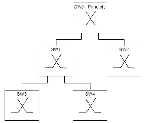
In HS1760 applications, the fabric is only allowed to be structured as a tree as shown in Fig. 2. The switch at the head of the tree is the principle switch. The principle switch is statically configured with the Domain Topology Map for the entire network. At startup, the principle switch distributes the Topology Map to the downstream switches in the fabric. The topology map contains the statically allocated addressing for the nodes of the network.
B. FC-AE-1553
HS1760 specifies FC-AE-1553 as the ULP to be used for command/control, and file transfer over the aircraft to store interfaces. FC-AE-1553 can generally be thought of as a mapping of MIL-STD-1553 onto a Fibre Channel network. Just like MIL-STD-1553, FC-AE-1553 uses a command response protocol with a controller (Network Controller) initiating read and write commands to the terminal (Network Terminals).
MIL-STD-1553 | FC-AE-1553 | |
Speed | 1 Mbps | 1 Gbps |
1553 Bus Entities | Bus Controller Remote Terminal RT Subaddress | Network Controller Network Terminal NT Subaddress |
Full Duplex | No | Yes |
Address Range | 31 RTs 30 SAs per RT | 16M NTs (24-bit Addr) 4G SAs per NT |
Bytes per Message | Upto 64 bytes | Upto 128 MB |
Bus Length | 100 Meters | Unlimited with switched topology |
Drop/Stub Length | 3 Meters | 30 Meters |
Table1. MIL-STD-1553 vs FC-AE1553
FC-AE-1553 provides a much larger addressable range of terminals and terminal subaddresses than MIL-STD-1553 as shown in Table 1. However, for compatibility with existing MIL-STD-1553 applications, the Subaddresses 1 to 30 are left reserved in FC-AE-1553. Also, in addition to the command/response protocol, FC-AE-1553 also includes provisions and protocol options to support file transfers and mass data transfers in order to to support more efficient data loading type applications.
III. HS1760 TEST AND SIMULATION
FC-AE-1553 provides a much larger addressable range of terminals and terminal subaddresses than MIL-STD-1553 as shown in Table 1. However, for compatibility with existing MIL-STD-1553 applications, the Subaddresses 1 to 30 are left reserved in FC-AE-1553. Also, in addition to the command/response protocol, FC-AE-1553 also includes provisions and protocol options to support file transfers and mass data transfers in order to to support more efficient data loading type applications.
A. Test Scenarios
HS1760 test equipment and test systems must be capable of providing support for the FC-AE-1553 Network Controller (NC) and Network Terminals (NT) as well as the avionics environment (AE) switch interfaces. Several test scenarios must be considered when designing test systems. For example:
- Testing at the interface to the stores
- Testing at the interface to the aircraft Stores Management System (SMS)
- Testing at the interfaces to a carriage
The Fibre Channel protocol defines several port types which are used for interfaces between nodes and switches. The details and requirements of the communications are defined based on the connected port types. In an HS1760 network, several port types must be considered.
1) N-Port
A Node Port is a port that resides at an end node such as a store. An N-Port connects to a fabric (fabric topology) or another N-Port (point-to-point topology).
2) F-Port
A Fabric Port is a port on a switch that connects to a node.
3) F/AE-Port
A Fabric/Avionics Environment port is a switch port that can support either connections to a node (acts like an F-Port) or to another AE switch.
Fibre Channel defines several other port types, for example to support arbitrated loop topologies. These additional port types are not mentioned here because they are not allowed in HS1760 networks. Fig 3 shows the location that the port types reside within a typical HS1760 network.
B. Testing HS1760 Stores
An HS1760 aircraft store operates as an FC-AE-1553 NT and is controlled by the SMS which acts as the NC. To test a store the test system must be capable of simulating the commands of the SMS NC. In the most simple HS1760 network scenario, the SMS can connect to the store via a point-to-point Fibre Channel connection. However, more commonly the NC of the SMS will be connected to multiple stores via a fabric.
Note: fabric switches are commonly capable of supporting point to point topologies and functioning as a hub which simply provides an interconnect between N-Ports at the end nodes
In order to have the capability to test all of the possible interface types at the MSI, the test system must have the capability to connect to the store using either Fibre Channel point-to-point or fabric topology.
C. Testing Stores Management Systems
A test system used to verify the operations of an SMS must have the capabilities to simulate the interface to both stores and to carriages at the ASI. For this testing scenario, the test system must have the capability to act as an N-Port and an FC-AE-1553 NT to simulate a store. The test system must also have the capability to act as multiple NTs and to present an F/AE-Port to the SMA ASI interface.
D. Testing the Carriage
To test an HS1760 Carriage, the test system must have the capability to simulate the signals at the CSI and CSSI. At the CSI, the test system will be required to simulate the FC-AE-1553 NC of the SMS as well as the F/AE-Port functions of the SMS AE switch. On the stores side of the carriage, the test system must simulate the N-Port and NT of one or more stores that may be attached to the carriage.
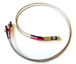
This can most easily be achieved by employing the use of a Small Form-factor Pluggable (SFP) transceiver capable of the 2.3V signaling over coaxial cables. Most Fibre Channel interface hardware provides SFP receptacles which can be used to host SFP transceivers.
IV. HS1760 TEST SYSTEM DESIGN
A. Test Equipment Connections
The HS1760 profile of Fibre Channel defines a 2.5 VPtP electrical signal over 75 Ohm coaxial cabling rather than the more commonly used optical media employed in Fibre Channel applications. Any HS1760 test and simulation equipment must therefore have the capability to communicate with the unit or systems under test over this electrical interface.
B. End Node Simulation
As shown in Table 1, the FC-AE-1553 protocol provides for much larger data transfers and a much larger addressable range of the terminals and sub addresses at each terminal when compared to MIL-STD-1553. It also provides for much higher data transfer rates.
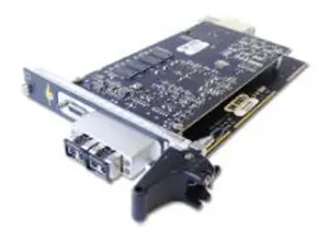
With these protocol enhancements in mind, it becomes clear that any test equipment used to support HS1760 verification activities must be implemented on latest high speed test system platforms. A PXI Express based system is an ideal solution which can provide up to 8GB/sec of dedicated bandwidth to each test instrument. The PXI Express instruments should be used to provide FC-AE-1553 NC and NT functions.
The test instruments must also provide SFP receptacles in order to be capable of hosting the AS5653 SFP transceivers required to interface to the HS1760 75 Ohm coaxial electrical interface. The test instrument must be capable of providing support for both the point-to-point and fabric topologies.
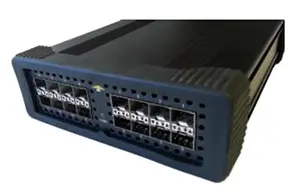
C. Avionics Environment Switches
For more complex test scenarios and system integration and simulations, the test system may require an avionics environment switch capable of FFI. The switch could be used together with the PXI Express test instrument, acting as an NC, to build a simulated SMS capable of interfacing to one or more stores.
The switch could also be used together with the PXI Express instrument(s) to emulate a carriage with attached stores. In this case, with an SMS as the unit under test, the lab switch would provide an F/AE-Port interface to the SMS. PXI Express instruments, operating as NTs, connected to the switch would simulate the downstream stores.
V. CONCLUSIONS
The latest version of MIL-STD-1760, MIL-STD-1760E, provides a new high speed signaling interface for increased bandwidth between the aircraft and external stores.
While this interface has been designed to be fully compatible with existing interface signals and connectors, it has also provided support for additional configurations of carriages and stores by introducing the option of a switched network architecture rather than a just the shared bus architecture provided by MIL-STD-1553.
It has also introduced new protocols such as FC-AE-1553 into the interface. As a result of these upgrades, test system designers must consider the demand for increased bandwidth in systems used to support design and verification of HS1760 stores and stores management systems.
Additionally, the test system designers must also consider the requirements to support new upper layer protocols such as FC-AE-1553 and also less common electrical interfaces such as the 75 Ohm coaxial interface employed by HS1760.
VI. REFERENCES
- INCITS TR-42-2007 , INCITS Technical Report for Information Technologiy-Fibre Channel-Avionics Environment-Upper Layer Protocol (FC-AE-1553),
- MIL-STD-1760E, 25 October 2007
- AS5653B, High Speed Network for MIL-STD-1760, 03 January 2014
About Avionics Interface Technologies (AIT)
AIT has gained the reputation for having the most technologically capable products with quick delivery times, high reliability, and unprecedented support. Our wide market acceptance stems from quality products and services worldwide. Expert pre- and post-sales technical support comes as part of the AIT solution. Our direct AIT offices, in cooperation with our network of qualified representatives, provide optimized in-country service and support for all your avionics flight, test, and simulation requirements.To provide local service and technical support for our valued customers, AIT has distribution and support offices worldwide. We have field offices in Arizona, Massachusetts, New Hampshire, and Ohio; and we use local authorized manufacturers’ representatives throughout the US and Canada for quick response. AIT also has a separate a production and design center based in Dayton, Ohio, just outside of Wright Patterson Air Force Base, for the design and development of our Fibre Channel products to support the F-35 Joint Strike Fighter.
We're Here to Help
Resources
Related Companies