Data Acquisition in High Speed Ethernet & Fibre Channel Avionics Systems
As avionics applications grow in complexity and sophistication, these systems are increasingly turning to the use of high speed serial data networks based on Ethernet and Fibre Channel to meet the ever increasing demand for data bandwidth.
As these types of networks become more common in new avionics systems, new and unique solutions are required for flight test data acquisition. This paper addresses several of the key considerations which much be addressed when designing a flight test system for the acquisition of avionics Ethernet and Fibre Channel data.
I. INTRODUCTION
In the past avionics systems have commonly been based on shared data bus technologies such as MIL-STD-1553 and ARINC 629. However as avionics systems have become more complex they are requiring more data bandwidth.
As a result, systems designers are turning to the use of networked systems based on Ethernet and Fibre Channel technologies. These networked systems provide both increased bit rates and the throughput advantages of a switched network (as opposed to shared bus architectures). In contrast to legacy systems such as MIL-STD-1553, Fibre Channel and Ethernet provide several bit rate and physical medium options as summarized below.
Protocol | Topology | Medium | Bandwidth |
MIL-STD-1553 | Shared Bus | Electrical (Manchester) | 1Mbit/s |
ARINC 629 | Shared Bus | Electrical (Manchester) | 2Mbit/s |
Ethernet | Switched Network | Electrical & Optical | 10Mbit/s 100Mbit/s 1000Mbit/s 10 Gbit/s |
Fibre Channel | Switched Network, Arbitrated Loop | Electrical & Optical | 1 Gibt/s 2 Gbit/s 4 Gbit/s |
Table 1. Avionics Communication Technology Comparison
A. Avionics Ethernet
Ethernet is a widely used data network technology which provides many standardized options to support a variety of bit rates and physical media. The most commonly used variants (in avionics systems) are:
Ethernet Type | Speed | Medium |
10BASE-T | 10Mbit/s | Copper |
100BASE-T | 100Mbit/s | Copper |
1000BASE-T | 1Gbit/s | Copper |
1000BASE-SX | 1Gbit/s | 860nm fiber |
10GBASE-SR | 10Gbit/s | 850nm fiber |
Table 2. Common Ethernet Variants
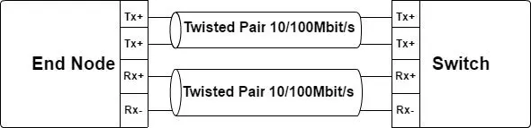
There are Ethernet PHY interfaces commonly available which support 10BASE-T, 100BASE-T, and 1000BASE-T (copper) Ethernet operations. Because these 3 variants utilize the same physical layer (copper twisted pair) and because Ethernet provides an link speed auto-negotiation mechanism, BASE-T networks are extremely common and easy to integrate.
Optical gigabit Ethernet (1000BASE-SX) is currently the most common variant of optical Ethernet while 10G Ethernet (10GBASE-SR) is largely viewed as the next major step for Ethernet based networks.
In the avionics environment, all of the previously mentioned Ethernet variants are used. There are also avionics specific Ethernet based protocols which provide definitions that profile Ethernet to provide real-time and fault tolerant operations often required in avionics applications.
ARINC 664 specifies an Ethernet profile for use in avionics systems. ARINC 664 type networks are used on several new commercial aircraft such as the Boeing 787 and Airbus 380. ARINC 664 profiles Ethernet to provide guaranteed worst case latency through the network between communicating end nodes. It also adds redundancy to achieve a level of fault tolerance. AFDXTM is a proprietary implementation of ARINC 664 defined by Airbus.
Time Triggered Ethernet (TTE) is another avionics focused Ethernet profile. TTE is defined in SAE AS6802 and can be considered an extension of ARINC 664. TTE adds determinism to ARINC 664 by utilizing a network wide communications schedule which guarantees no contention for link bandwidth in the network. On each link, the transmitting nodes only send data at prescheduled times when no other traffic is guaranteed to be on the network.
ARINC 664, AFDXTM, and TTE utilize 10BASE-T, 100BASE-T, 1000BASE-T, and 1000BASE-SX Ethernet. All of these Avionics specific protocols are fully compliant with standard IEEE 802.3 Ethernet. They only profile the use of Ethernet.
B. Fibre Channel In Avionics
The Fibre Channel protocol is specified by the INCITS T11 committee. Fibre Channel was originally developed to support the storage area network (SAN) industry. However, the T11 committee has also defined several Avionics Environment (AE) documents specifying the use of Fibre Channel in avionics systems. The table below summarizes some of the most common Fibre Channel Avionics Environment (FC-AE) specifications.
Specification | Description |
FC-AE-ASM | The Asynchronous Subscriber Messaging protocol supports the publishing of small amounts of periodic data which is consumed by multiple subscribers. ASM is intended to support the publishing of typical periodic avionics data on a network. |
FC-AE-RDMA | Remote Direct Memory Access is used to transfer and stream large amounts of data or files across the avionics network. RDMA communications are typically more asynchronous than periodic. |
FC-AE-1553 | FC-AE-1553 is a mapping of the legacy MIL-STD-1553 protocol onto a Fibre Channel network. This was developed to support HS1760 weapons interfaces |
Table 3. FA-AE Protocols Summary
In addition to the FC-AE protocols, ARINC 818 (FC-AV) defines the use of Fibre Channel in avionics display systems. The FC-AE protocols are most commonly found on military aircraft platforms while ARINC 818 is most commonly found in commercial aircraft.
Of the previously mentioned Fibre Channel protocols, only FC-AE-1553 uses an electrical physical interface. Avionics Fibre Channel systems most commonly use 1Gbit/s and 2Gbit/s optical physical interfaces.
II. FLIGHT TEST DATA ACQUISITION REQUIREMENTS
A. Overview
During flight test of new aircraft avionics systems, network data must be acquired and archived (recorded) for post flight analysis. Additionally, some key network data must also be captured and made immediately available for live monitoring and analysis.
B. Live Flight Test Data
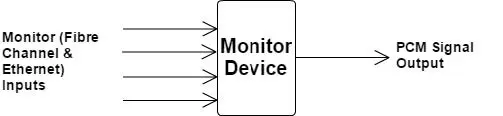
Some data acquired from avionics systems must be monitored live at a ground station during the execution of flight tests. This live data is captured by monitoring equipment on the aircraft and then communicated to the ground on a Pulse Code Modulation (PCM) signal by an onboard telemetry system. At the ground station this data can be viewed by test engineers during the flight test. Additionally, the data from the aircraft system may be recorded for post processing at the ground station. The PCM data stream from the aircraft can typically provide a bandwidth between 1.25 Mbit/s and 20 Mbit/s.
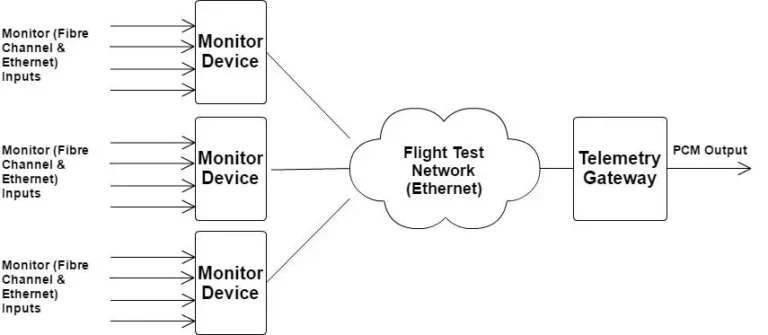
A common strategy within a flight test telemetry system is to select a set of avionics systems parameters of interest for the particular flight test, and to arrange a periodic schedule on the PCM link (consisting of frames and sub-frames) so that the data parameters of interest are sampled and transmitted to the ground station at a pre-defined rate. In some cases the telemetry system producing the PCM stream of data may be part of the same system that is monitoring (sampling) the avionics network data. Another strategy that is often employed is to have multiple monitoring devices which transmit the sampled avionics network data over an in-vehicle test data network (Ethernet) to a telemetry gateway which converts in the incoming stream of network data parameters to a PCM stream for transmission to a ground station.
C. Post Flight Analysis (Data Recording)
During a flight test, in addition to transmitting live data to ground stations, it is also often a requirement to capture and record data to an in-vehicle flight data recorder. The flight data recorder most commonly will have the capability to ingest data on one or more Ethernet input interfaces. Currently, 1 Gbit/s (1000BASE-T) Ethernet is the most common input interface for flight data recorders.
A common strategy for flight data recording, that is supported by currently available flight data recorders, is to configure the recorder to simply receive and stream data destined to User Datagram Protocol (UDP) port to an archive file in the data recorder. It is possible in some cases to stream data to multiple files by addressing the data to different UDP ports at the recorder. For data captured from Ethernet and Fibre Channel networks, there are a variety of standard methods available to encode the captured data into the UDP data stream to the recorders. One of the most common encoding schemes is defined in IRIG 106 Chapter 10. This specification defines a standard header to be added to the monitored network frames in order to hold a timestamp and additionally error detection information about the captured networks data (such as CRC errors and data length errors). Because IRIG 106 Ch.10 is a well accepted standard in the flight test community, there are an abundance of software tools readily available for processing and analyzing IRIG 106 Ch.10 formatted flight test capture data.
Another possible encoding format for captured Fibre Channel and Ethernet avionics network data is the use of the PCAPNG format. The PCAPNG format is a well defined archive format that includes support for both Fibre Channel and Ethernet frame data. Similar to the IRIG 106 Ch.10 format, the PCAPNG format provides a standard format for attaching timestamps and error information to captured avionics network frames. While IRIG 106 Ch.10 is a well accepted standard in flight test communities, the PCAPNG format is the most widely used and accepted in the IT and data networking communities and as a result there is also an abundance of readily available software tools for processing and analyzing PCAPNG formatted capture data.
III. ACCESSING DATA IN SWITCHED NETWORKS
A. Two Approaches
In shared bus systems, such as MIL-STD-1553, all of the avionics data can be acquired from a single point of connection on the bus. This is not the case in switched networks like Ethernet and Fibre Channel. In a switched network there are two possible approaches to accessing the network data for acquisition.
One approach is to use a “monitor” port on the network switches. With this approach, the routing tables for the network data through the switches must be modified such that the data which is to be acquired is routed to a special physical port on the network switch in addition to the its intended destinations. The flight test monitoring equipment or flight test data recorder is connected to these monitor ports. An advantage of this approach is simplified wiring. Once the monitoring equipment is attached to the monitor port of the network switch it can acquire all needed data by only “soft” changes to the switch routing tables and without the need for re-wiring to gain access to additional network data. However, a drawback of this approach is that since the data is routed to this monitor port it can only be timestamped by the monitoring equipment once it reaches the monitor port, so some information about timing and ordering of the data on the network is lost. Also, since the avionics network switch tables are modified to support the acquisition of data, it can be argued that the behavior of the network is also modified or affected by the acquisition system.
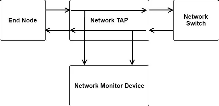
An alternative to the use of monitor ports is the use of network taps. A network tap is a device that is used to access the physical network link between communicating systems such as an end node and a switch. With a network tap, the monitoring equipment is given access to the data on the link at specific points in the network rather than at a single switch port to which it has been routed. With this approach, data can be captured with accurate timestamping when it occurs on a link and the network switch routing tables are not modified. So, data is collected without changing the behavior of the avionics system and a more accurate measure of data ordering and time can be acquired. The down side of this approach is increased complexity in the wiring of the data acquisition system since taps and monitoring equipment must be setup at several locations within the physical network.
Because of the provided advantages with respect to supporting accurate timing and data ordering in acquired data and in spite of the complexity in wiring, the use of network taps is the preferred approach in avionics network data acquisition.
B. Network Taps
A network tap is a device which provides access to the data flowing in both directions on a bi-directional link between communicating systems in a network (most commonly between an end node and a network switch). A bi-directional network tap will commonly have four physical ports: one port for the connections to the network system, one port for connection to the network switch, and two ports for connections to monitoring equipment. Each monitoring port provides a stream of data from one of the data directions on the bi-directional link being monitored.
There are generally two types of network taps to consider: active taps, which require external power, and passive taps, which do not require external power.
1) Passive Taps
Passive network taps are commonly used in optical networks and can be thought of as a simple light divider. This type of tap simply “splits” the optical signal as it passes through to provide two outputs, the pass through and the monitor output. A passive, splitter tap is characterized by a split ratio which specifies how much of the signal power goes to the pass through and how much of the signal power goes to the monitor. The desired split ratio can depend on the type of receiving equipment and the length of the links to the remote device and the monitoring equipment. Signal splitter taps are most commonly used for optical networks such as Fibre Channel and Ethernet 1000BASE-SX and 10GBASE-SR.
Passive taps are also available for 10/100BASE-T networks and just like their optical counterparts they are largely simple signal splitters because with 10BASE-T and 100BASE-T Ethernet, the signals are carried in each direction of a bi-directional link on 2 different differential pairs.
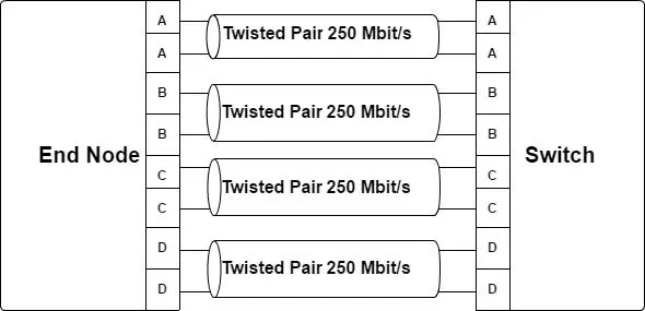
Because of the complexity of supporting 1 Gbit Ethernet over a copper medium, passive taps are not currently available for 1000BASE-T Ethernet. 1000BASE-T Ethernet requires the use of all 4 twisted pairs available in standard Ethernet CAT5e/6 cabling. This type of cabling can only reliably support up to 250Mbit/s on a single pair. To achieve 1Gbit/s the 4 pairs are used in parallel to send 4 bits in both directions simultaneously. The sharing of a single pair for simultaneous data streams in both directions is achieved by complex physical interfaces which subtract out the transmitted signal from the received signal at each end to extract the original signal from the remote node. For this reason, a signal splitter does not work because the monitor is not able to recover the original transmitted signal because it does not have access to the information required to subtract out or separate the signal.
2) Active Taps
Passive taps are generally preferred for avionics network data acquisition because they do not require external power and are simple by design and therefore provide a much lower risk of disrupting the monitored avionics system in the case of failure. However because passive taps are not available for 1 Gbit/s copper Ethernet, an active tap must be used for this type of network. The active taps must contain Ethernet PHY components which receive the signals and forward them on to the link partner in each direction and to Ethernet PHY components at the monitor interfaces of the tap. Obviously there are drawbacks to the use of these types of devices. If there is a power loss at the device, the link between the avionics systems nodes could become disabled. To combat this, most 1000BASE-T taps contain a fail over mechanism which is implemented in a bypass switch which defaults the tap to a physical signal pass through during power loss.
IV. DATA AGGREGATION
A. Overview
As discussed previously, the preferred method of data acquisition for flight test applications is the use of network taps within the avionics network. With the use of network taps, the flight test data acquisition system can access data from multiple points in the network to get the most accurate picture of the behavior and operations of the network. With the network tap strategy, there are two network ports required to monitor each network location which is tapped (one monitor port do data in each direction on the bi-directional links). As a result of this, the network tap approach results in a large number of required monitor interfaces. Therefore to handle this large number of interfaces a monitoring device is desired which can aggregate the data from a number of monitor interfaces onto a single (or small number of) Ethernet interface to a flight test data recorder. Additionally, to be able to simultaneously support the live data requirements for flight test applications, it is also desirable for the aggregator device to have the capability to select and output data to a PCM interface and/or to a telemetry gateway over a flight test network on the vehicle under test.
B. Aggregating Data to Flight Test Data Recorders
Because avionics networks can be composed of combinations of Ethernet and Fibre Channel network types (different speeds and physical media) an avionics network data aggregator device must be capable of monitoring data from a variety of network types. The aggregator must also have the capability to accurately timestamp the monitored data as it is received so that the ordering of the information can be reconstructed from the flight data recorder archives. Also, so that the recorded data may correlated to other aircraft events, the timestamp clock of the network data aggregator must be capable of being synchronized to external reference clock signals such as IEEE 1588 and IRIG-B. The aggregator device must also package the captured Fibre Channel and Ethernet network data into a format such as IRIG 106 Chapter 10 or PCAPNG as described previously since these data formats provide standard methods for the aggregator to indicate timestamps and error information for the captured data.
C. Recorder Data Filtering and Selection
The data inputs of the flight data recorders are limited to the link speed at the inlets (typically 1 Gbit/s Ethernet with 10Gbit/s expected in the near future). With the data aggregator expected to capture from a dozen or more network interfaces which can host data streams up to 1 or 10 Gbit/s in each direction, the aggregator can easily monitor and capture more data than the input of the recorder can accept. Therefore the aggregator must have the capability to also filter the Fibre Channel and Ethernet data captured prior to streaming to the data recorders in order to reduce the data flow to the maximum allowed by the recorder. The filters must allow the flight test engineer to select (or filter) data frames based on Fibre Channel and Ethernet frame header fields (source and destination addresses for example).
D. Telemetry Data Selection
Just as the data recorder maximum input capacity limits the amount of network data that can be archived; the limited bandwidth available on telemetry links also requires that the avionics network data aggregator provide the ability to select data parameters from the monitored Fibre Channel and Ethernet monitor inputs for transmission on the telemetry interfaces. While network data recorders provide a bandwidth limit in the range of gigabits per second, the telemetry interface provides much more restrictive bandwidth limits which are in the range of several Mbit/s. So, while the data filters for the selection of data to be aggregated to the recorder must allow the selection of whole Ethernet and Fibre Channel frames based on addressing fields in the protocol headers, the data selection for telemetry data must additionally allow for selection of bit and byte fields within the payload of network data frames. In order to support both telemetry data strategies described previously (See Figure 1 and Figure 2) the network data aggregator must allow the selected telemetry data to be transmitted directly on a local PCM interface or to alternatively be sent to a telemetry gateway via an Ethernet output interface.
V. CONCLUSION
As avionics communications systems shift increasingly to switched network technologies based on Fibre Channel and Ethernet, new approaches to flight test data acquisition must be evaluated since these networks do not provide a single connection point from which all network information can be accessed at the time it occurs on the network. The preferred approach to access data in a switched network avionics system is the use of network taps to provide access to the avionics data at multiple points of interest in the network. The use of the network tap approach has the effect of requiring the monitoring of a large number of network interfaces. Due to this large number of monitored interfaces and due to the large bandwidth capacity of these networks, captured data must be filtered and aggregated from a large number of monitored interfaces onto limited bandwidth input interfaces to flight data recorders and onto even more bandwidth restrictive telemetry interfaces. Avionics Network Data Aggregators are a new class of device that have been developed to provide data filter, selection and aggregation functions in these switched network environments.
About Avionics Interface Technologies (AIT)
AIT has gained the reputation for having the most technologically capable products with quick delivery times, high reliability, and unprecedented support. Our wide market acceptance stems from quality products and services worldwide. Expert pre- and post-sales technical support comes as part of the AIT solution. Our direct AIT offices, in cooperation with our network of qualified representatives, provide optimized in-country service and support for all your avionics flight, test, and simulation requirements.To provide local service and technical support for our valued customers, AIT has distribution and support offices worldwide. We have field offices in Arizona, Massachusetts, New Hampshire, and Ohio; and we use local authorized manufacturers’ representatives throughout the US and Canada for quick response. AIT also has a separate a production and design center based in Dayton, Ohio, just outside of Wright Patterson Air Force Base, for the design and development of our Fibre Channel products to support the F-35 Joint Strike Fighter.
We're Here to Help
Resources
Related Companies