Better Alternative for Measuring Linearity of GaN Amplifiers
APPLICATION NOTE: Methods to measure the true linearity of a power amplifier
GaN devices continue to be a key element in many radar, electronic warfare, satellite and terrestrial communication systems. GaN devices offer a number of advantages. For example, GaN devices have a high breakdown field due to a large bandgap that enables them to operate at higher voltages. Combining this with a high saturation velocity and corresponding large charge capability, GaN devices are ideal for high power applications. Adding excellent thermal conductivity, it is easy to see why the utilization of GaN devices continues to grow. In a recent study, Yole Développement expects the GaN industry to grow with a 23% CAGR between 2017 and 2023, driven by telecom and defense applications.
Some of the most popular GaN devices are wideband RF power amplifiers. Amplifiers are described by multiple characteristics including gain, frequency response or bandwidth, power output, linearity, efficiency, and noise figure. Two key characteristics that are often used to describe the quality of an amplifier are linearity and efficiency. The relative importance of the two attributes depends upon the application. For example, in a satellite-based application, efficiency may be more important as there is limited power available on a satellite. In terrestrial wireless communications, the relative importance may be more equal. Communication systems, such as those based on 5G standards, utilize wideband modulation schemes with significant linearity requirements. In addition, because of the amount of base stations needed to support the systems, it requires acute attention to power efficiency to manage operating expenses. Unfortunately, the power levels to maintain amplifier linearity are often well below the drive levels needed for maximum efficiency.

LINEARITY vs EFFICIENCY
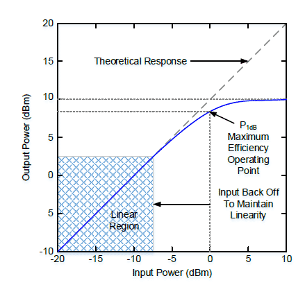
This article will focus on the applications in which amplifier linearity is the critical attribute. In Figure 1, the blue line illustrates typical amplifier behavior. Linearity is measured by increasing the input power and observing the output power until the amplifier enters compression. Often amplifier linearity is specified at the input power level at which corresponding output power is 1 dB lower than the theoretical linear response, P1dB, which has been historically considered the point at which amplifiers operate most efficiently.
With the simultaneous need for linearity and efficiency, it is crucial to optimize the input back off (IBO) value. Too much back-off sacrifices efficiency and causes the amplifier to be oversized and costlier (to reach the required output power), while too little brings increasing compression and signal degradation. Therefore, measuring amplifier linearity accurately under realistic operating conditions is of considerable value to GaN engineers.

LINEARITY ASSESSMENT ALTERNATIVES
There are a number of alternatives for measuring and expressing amplifier linearity. Three common methods are: 1) characterization of amplifier intermodulation distortion (IMD), 2) noise power ratio (NPR) measurements, and 3) crest factor (CF), or peak-to-average power ratio (PAPR) measurements.ed with the LA-5 linearizing electronics. The meter is supplied with an extended range calibration to give a turndown of 100:1 over the flow range. It can be supplied with either meter-mounted or remote-mounted electronics. High temperature amplified pickoffs are used to eliminate noise generated by the floating (non-grounded) electrical system of the turbine generator. The FT Series turbine meter can be placed inside the generator room due to its compact size and durability under extreme conditions.With the simultaneous need for linearity and efficiency, it is crucial to optimize the input back off (IBO) value. Too much back-off sacrifices efficiency and causes the amplifier to be oversized and costlier (to reach the required output power), while too little brings increasing compression and signal degradation. Therefore, measuring amplifier linearity accurately under realistic operating conditions is of considerable value to GaN engineers
LINEARITY ASSESSMENT TOOL COMPARISON
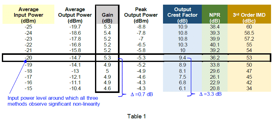
The linearity of an amplifier was measured with all three approaches. Using a Noisecom noise source or a two-tone source, a signal was applied to the amplifier starting from -25 and increased in one dB steps until reaching -15 dBm. The results for each measurement are shown below. Reductions in gain, crest factor, NPR, and the delta between intermodulation products and the carrier signals all indicate an amplifier is behaving non-linearly.

Continue Reading White Paper here:
Contact your local VMA field engineer today if you need help or have any additional questions.


